Preamble
VHDL stands for Very High Speed Integrated Circuit Hardware Design Language. No, I’m not kidding. Despite being a mouthful, the language is used by engineers to prototype and describe industrial digital logic.
This document started as a copy of living notes for the CEG3155 course I was taking, Digital Systems II. It lives on as I implement MIPS processors in CEG3156, Computer System Design.
The two primary types of VHDL logic the course deals with (and I deal with within this document) are called concurrent and sequential, where concurrent logic obviously runs concurrently, and sequential logic runs sequentially within process statements.
A Basic VHDL Program
Let’s dive right in with a full example. Here is an implementation for a decoder with an enable bit. Note the two primary sections of the program: entity, and architecture.
library ieee;
use ieee.std_logic_1164.all;

entity decoder_2x4b is
  port(
    a, b, en : in std_logic;
    d : out std_logic_vector(3 downto 0)
  );
end decoder_2x4b;

architecture structural of decoder_2x4b is
begin
  d <= "0000" when (en='0') else
    "0001" when (a='0' and b='0') else
    "0010" when (a='0' and b='1') else
    "0100" when (a='1' and b='0') else
    "1000" when (a='1' and b='1');
end structural;
The first thing that our program requires is the standard IEEE 1164 libraries.
These should always be present at the top of your programs to use constructs
like std_logic.
library ieee;
use ieee.std_logic_1164.all;
After importing libraries, we describe our entity by providing the inputs and
outputs. Here, a, b, and en are of type std_logic, a simple binary
operator that can hold 0 or 1. Our output is a std_logic_vector, which is
an array of std_logic objects. The notation 3 downto 0 will create four
output bits.
entity decoder_enable is
  port(
    a, b, en : in std_logic;
    d : out std_logic_vector(3 downto 0)
  );
end decoder_enable;
After describing our entity, we describe the internals of the entity with an
architecture block. The output d is written to with the arrow operator <=,
and using when and else statements. The first condition that is true will be
written to the output d.
architecture structural of decoder_2x4b is
begin
  d <= "0000" when (en='0') else
    "0001" when (a='0' and b='0') else
    "0010" when (a='0' and b='1') else
    "0100" when (a='1' and b='0') else
    "1000" when (a='1' and b='1');
end structural;
This logic is technically concurrent. Each assignment (<=) will run
simultaneously when the signal reaches the component. Note that only a single entity can be defined per VHDL file.
Internal Signals
Signals can be used to redirect logic within a component. Inputs cannot be written to, and outputs cannot be used for input to other systems, so signals are used to ferry internal outputs to internal inputs.
--- Assume w, x, y, z are used as inputs.
architecture arch of and_4 is
  signal a, b : std_logic;

  begin
    a <= w and x;
    b <= y and z;
    output <= a and b;
end arch;
Inclusion of Components
Large digital systems can be implemented by combining large amounts of components defined in other VHDL files. We accomplish this with internal signals and component statements.
For instance, a trivial NAND component with one input and output can be defined in its own VHDL file, like so:
library ieee;
use ieee.std_logic_1164.all;

entity nand is
  port(
    x, y : in std_logic;
    z : out std_logic
  );
end decoder_enable;

architecture nand_arch of nand is
begin
  y <= not (x and y);
end nand_arch;
If you were to use this in another VHDL architecture, you would first have to
place nand.vhdl in the same directory, then you could write an architecture
like the following:
architecture sample_arch of big_component is
  signal H : std_logic_vector(1 downto 0);

  component NAND
    port(
      x, y : in std_logic;
      z : out std_logic
    );
  end component;

  begin
    L0: NAND(
        x => SW(0),
        y => SW(1),
        z => H
    );

    LEDR(0) <= H;
end sample_arch;
A Complete Example
Here, we use the previously created decoder with file-name decoder_2x4b.vhd to
create a complete, deployable example that uses the switches, 7-segment
displays, and buttons on the Altera DE-1 Cyclone II EP2C20F484C7N. Our example
will utilize these three files:
top.vhddecoder_2x4b.vhdencoder_7seg.vhd
All we are going to do is connect our decoder to a set of switches and lights. When programming for upload on an Altera board, a pin assignment file can be used to easily access the following pins:
SW, a set of switches.KEY, a set of push-buttons.HEX#, a collection of seven-segment displays.LEDG, a set of green LEDs over the push-buttons.LEDR, a set of red LEDs over the switches.
Referring to the section on component inclusion, we can connect our decoder inputs to two switches, and the outputs to four green LEDs.
DECODER0 : decoder_2x4b port map(
  a => SW(1),
  b => SW(0),
  en => '1',
  d => LEDG(3 downto 0)
);
At this point, after adding inputs and outputs (Quartus will automatically map
inputs with mappings to the correct pins,) your top.vhd should appear like so:
library ieee;
use ieee.std_logic_1164.all;

entity top is
  port(
    SW : in std_logic_vector(9 downto 0);
    KEY : in std_logic_vector(3 downto 0);
    LEDR : out std_logic_vector(9 downto 0);
    LEDG : out std_logic_vector(7 downto 0)
  );
end top;

architecture structural of top is

  component decoder_2x4b is
  port(
    a, b, en : in std_logic;
    d : out std_logic_vector(3 downto 0)
  );
  end component;

begin

  LEDR <= SW;

  DECODER0 : decoder_2x4b port map(
    a => SW(1),
    b => SW(0),
    en => '1',
    d => LEDG(3 downto 0)
  );

end structural;
Now we can use physical switches to test our decoder!
In addition to this, add the following component as encoder_7seg.vhd to your
project to make use of the seven-segment displays:
library ieee;
use ieee.std_logic_1164.all;

entity encoder_7seg is
  port(
    word_in : in std_logic_vector(3 downto 0);
    hex_out : out std_logic_vector(6 downto 0)
  );
end encoder_7seg;

architecture structural of encoder_7seg is
begin
  with word_in select hex_out <=
    "1000000" when x"0",
    "1111001" when x"1",
    "0100100" when x"2",
    "0110000" when x"3",
    "0011001" when x"4",
    "0010010" when x"5",
    "0000010" when x"6",
    "1111000" when x"7",
    "0000000" when x"8",
    "0010000" when x"9",
    "0001000" when x"A",
    "0000011" when x"B",
    "1000110" when x"C",
    "0100001" when x"D",
    "0000110" when x"E",
    "0001110" when x"F",
    "1111111" when others;

end structural;
Looking back at the code, adding this component to our top file, and
connecting each HEX component to an input and HEX output yields the following
file:
library ieee;
use ieee.std_logic_1164.all;

entity top is
  port(
    SW : in std_logic_vector(9 downto 0);
    KEY : in std_logic_vector(3 downto 0);
    HEX0, HEX1, HEX2, HEX3: out std_logic_vector(6 downto 0);
    LEDR : out std_logic_vector(9 downto 0);
    LEDG : out std_logic_vector(7 downto 0)
  );
end top;

architecture structural of top is

  component decoder_2x4b is
  port(
    a, b, en : in std_logic;
    d : out std_logic_vector(3 downto 0)
  );
  end component;

  component encoder_7seg is
    port(
      word_in : in std_logic_vector(3 downto 0);
      hex_out : out std_logic_vector(6 downto 0)
    );
  end component;

begin

  LEDR <= SW;

  DECODER0 : decoder_2x4b port map(
    a => SW(1),
    b => SW(0),
    en => '1',
    d => LEDG(3 downto 0)
  );

  HEXd3 : encoder_7seg port map(
    word_in => SW(9 downto 6),
    hex_out => HEX3
  );

  HEXd2 : encoder_7seg port map(
    word_in => SW(5 downto 2),
    hex_out => HEX2
  );

  HEXd1 : encoder_7seg port map(
    word_in => x"0",
    hex_out => HEX1
  );

  HEXd0 : encoder_7seg port map(
    word_in => KEY,
    hex_out => HEX0
  );

end structural;
Our board can now:
- Decode switches 1 and 0 out to the first four green LEDs.
- Display switches 9-6 and 5-2 as HEX characters on the display.
- Display keys 3-0 as a HEX character on HEX0.
Now we can continue into advanced topics with good general knowledge of how to
create and run a simple VHDL program on a physical board. A complete copy of the
source code, including qpf project file and pin assignment file, can be found
on GitHub at
Projects/ vhdl/ cyclone_II_proof_of_concept
Concurrent/Structural VHDL
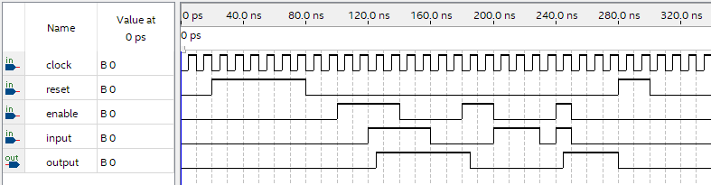
Concurrent statements are used to model real systems. For instance, a D Flip Flop can be modeled in structural style:
library ieee;
use ieee.std_logic_1164.all;

entity register_1 is
  port(
    input, enable, clock, reset : in std_logic;
    output : out std_logic
  );
end register_1;

architecture structural of register_1 is
begin

  output <= '0' when (reset = '1') else
        input when ( rising_edge(clock) and enable = '1');

end structural;
For an architecture to be considered as structural, process statements cannot be used within the body of the primary architecture.
Sequential/Behavioural VHDL
Process statements can be used to define logic with a familiar, imperative style. It is fine for creating test benches, but should not be used for modeling components which will be made into hardware.